
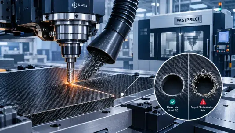
Composite materials such as carbon fiber reinforced polymer (CFRP), glass fiber laminates, and aramid blends are chosen for their strength-to-weight ratio. They are also some of the hardest materials to machine cleanly. A metal part that is cut a little too aggressively usually just shows a rough finish. A composite part cut the same way can split between plies, fray at the edges, or end up with holes that will not accept a fastener properly.
Two defects cause the most rejected parts: delamination and poor hole fit. Both are preventable when tooling, cutting parameters, fixturing, and process planning are treated as one connected system. This guide explains why these defects happen and what to change on the shop floor to stop them.
Why Composites Behave Differently Under a Cutter
Metal is uniform and ductile. It deforms and flows ahead of the tool. A composite laminate is a stack of fiber layers held together by a polymer matrix, and it behaves very differently:
- The material is anisotropic, so cutting forces act differently depending on fiber direction.
- Fibers are abrasive and wear tool edges quickly.
- The resin matrix softens with heat, which weakens the bond between plies.
- The interlaminar bond is far weaker than the fibers themselves, so forces pushing plies apart cause separation.
Because of this, the goal is not only to remove material. The goal is to shear fibers cleanly while keeping the load path on the laminate as low as possible.
Understanding What Triggers Delamination
Delamination is the separation of plies, and it usually starts at the entry or exit of a cut. Knowing the mechanism makes the fix easier to choose.
Push-Down and Peel-Up
When a drill or router enters the top ply, an upward-pulling helix can lift the layer instead of cutting it. This is called peel-up. At the exit side, the tool pushes the last plies outward before the fibers are severed. This is called push-down, and it is generally the more damaging of the two because the bottom plies have no support behind them.
Heat and Dull Tools
A worn edge rubs rather than cuts. Friction raises temperature, the matrix softens, and the plies lose bonding strength. Dull tools also raise thrust force, which multiplies the risk of both peel-up and push-down.
Poor Support
Unsupported laminate flexes under tool pressure. Even a small amount of vibration can create micro-cracks that grow into visible delamination after the part is released from the fixture.
Choosing Tooling That Protects the Laminate
Tool selection has the largest effect on edge quality. Standard high-speed steel and general-purpose carbide are rarely suitable.
| Tool Feature | Recommended Choice | Why It Helps |
|---|---|---|
| Coating | Diamond-coated (CVD) | Resists abrasive wear and holds a sharp edge |
| Substrate | Fine-grain carbide | Keeps the cutting edge stable |
| Router style | Compression (up-cut and down-cut) | Pushes fibers into the part on both faces |
| Drill geometry | Brad-point or dagger drill | Cuts fibers at the outer edge and lowers thrust |
| Point angle | Reduced thrust designs | Limits exit-side damage |
Compression routers deserve special mention. The lower flutes push the bottom plies upward while the upper flutes push the top plies downward. This locks the laminate together during the cut, which greatly reduces fraying on both faces.
Tools should also be replaced on a schedule, not only when a defect appears. Tracking tool life by linear distance cut or hole count keeps quality steady across a production run.
Setting Feeds, Speeds, and Cutting Strategy
The right parameters keep chip load high enough to cut cleanly while heat stays low. Some practical guidelines:
- Use higher spindle speeds with a moderate feed rate so each tooth removes a proper chip rather than rubbing.
- Avoid dwelling. Pausing at the bottom of a hole or in a corner creates heat.
- Reduce feed rate as the tool approaches the exit face to lower push-down force.
- Use climb milling where possible for a cleaner edge finish.
- Keep depth of cut consistent so cutting forces stay predictable.
For thick laminates, a step approach also helps. Peck drilling with a short retract clears dust, but each re-entry must be smooth. Many shops instead use orbital drilling, which cuts a hole using a helical toolpath with a smaller tool. Orbital drilling lowers thrust force, improves chip evacuation, and produces rounder holes.
Getting Holes to Fit Correctly
Poor hole fit shows up as oversized holes, out-of-round holes, fuzzy edges, or inconsistent diameters through the thickness of the laminate. The usual causes are tool wear, deflection, and heat.
Common Hole Defects and Fixes
| Problem | Likely Cause | Corrective Action |
|---|---|---|
| Oversized hole | Tool runout or wobble | Check holder and collet, reduce runout |
| Tapered hole | Tool wear along the flank | Replace tool earlier |
| Fuzzy or frayed entry | Peel-up from wrong geometry | Use a brad-point or up-cut and down-cut tool |
| Exit splintering | No backing support | Add a sacrificial backing plate |
| Burned resin ring | Excess heat | Increase feed, use sharp tools, add air blast |
| Out-of-round hole | Vibration or weak fixturing | Improve clamping and shorten tool stick-out |
Drill and Ream, Do Not Force It
For tight-tolerance fastener holes, a two-step process works better than a single pass. First drill an undersized pilot hole. Then finish with a reamer or an orbital finishing pass. This removes the roughest layer of damage and brings the hole to its final size with light cutting loads.
Control the Stack
Many aerospace and structural assemblies drill through composite and metal at the same time. Each material wants different parameters, so the process has to balance both. Sharp, coated tools and reliable chip extraction are essential, because metal chips dragged through a composite hole will score the bore wall and ruin the fit.
Fixturing and Backup Support
Even perfect tooling fails on a poorly held part. Good fixturing should:
- Support the laminate as close to the cut as possible.
- Use vacuum fixtures or soft clamping to avoid crushing the surface.
- Place a sacrificial backing plate under drilled areas so the exit plies stay supported.
- Avoid clamp pressure that distorts thin panels and springs back after release.
Dust management is part of fixturing too. Composite dust is abrasive and can contaminate machine components, so an effective extraction system protects both the operator and the equipment while keeping cutting zones clear.
How Multi-Axis Machining Improves Quality
Flat panels are the easy case. Real components often have curves, ribs, and compound surfaces, and cutting these with a fixed tool angle can cause the tool to enter the laminate at a poor angle, which raises the risk of delamination. This is where 5-axis machining for contoured composite parts delivers a real advantage. The tool can be kept normal to the surface throughout the cut, so entry and exit angles stay consistent and forces stay balanced. It also removes the need for multiple setups, which lowers the chance of misalignment between features and improves hole position accuracy.
Inspect Before the Part Leaves the Shop
Damage is not always visible. A part can look fine at the edge and still have internal separation. Recommended checks include:
- Visual inspection under magnification for fiber pull-out and frayed edges.
- Ultrasonic testing or thermography for internal delamination.
- Go/no-go gauges and bore gauges for hole diameter and roundness.
- Sampling first-off parts at the start of every run and after every tool change.
Recording the results helps the team spot tool wear trends before they become scrap.
Working With a Shop That Understands Composites
Process knowledge matters as much as machine capability. When you are sourcing machining custom composite components, look for a supplier that can explain its tooling strategy, its fixturing approach, and its inspection method in plain terms. Ask about tool life management, experience with your specific fiber and resin system, and how they verify hole quality on critical fastener locations. A shop that answers these questions confidently is far less likely to send you delaminated parts.
Final Thoughts
Delamination and poor hole fit are not random events. They come from predictable causes: dull or unsuitable tools, excess heat, unsupported laminate, and poor cutting strategy. Choosing diamond-coated or compression tooling, keeping feed rates well matched to spindle speed, supporting the part properly, and inspecting early will eliminate most of the problems that cause rejected composite parts.
Treat the process as a complete system, from tool selection to final inspection, and the results become repeatable, which is what production customers actually need.